Choosing a Geared Stepper Motor in 2026 requires more than comparing torque values online. Real applications expose weaknesses quickly. A motor that looks powerful on paper may stall under acceleration, heat up inside a small enclosure, or lose accuracy through gearbox backlash. The correct choice begins with the machine’s actual load, speed profile, mounting space, and operating environment.
This guide examines the factors engineers and equipment builders should verify before purchasing. It considers holding torque, output speed, reduction ratio, voltage, current, duty cycle, and thermal limits. It also explains how planetary, spur, and worm gearboxes behave in practical systems. A compact planetary gearbox may deliver strong precision, while a worm gearbox can offer useful self-locking behavior. However, efficiency and heat must be checked carefully. Do not trust one specification alone.
Measurements matter. Test the motor with the real load, coupling, cable length, and controller whenever possible. Listen for resonance near operating speeds. Check the gearbox after repeated reversals. Small errors become expensive later. A neat calculation can still mislead. I have seen designs fail because engineers ignored starting torque or assumed rated torque meant continuous torque. Manufacturer datasheets, test reports, and application support should guide the final decision. Yet supplier claims still deserve verification. By comparing performance, reliability, cost, and serviceability, readers can select a Geared Stepper Motor that fits the complete motion system, not merely the product page.
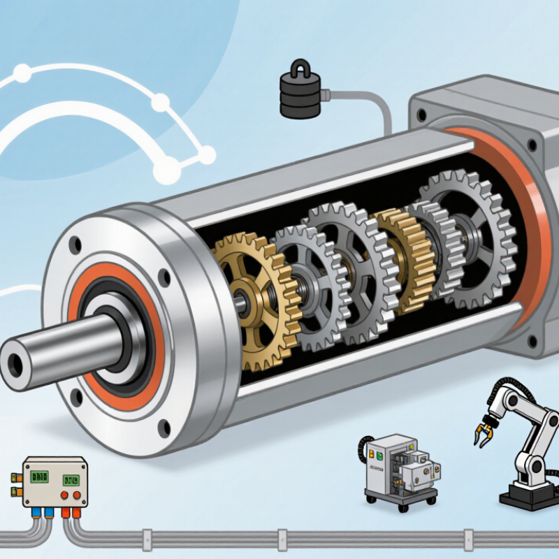
How to Choose a Geared Stepper Motor in 2026?
Define the application before comparing geared stepper motors. Measure the required load torque at the output shaft, not at the motor shaft. Include friction, gravity, startup resistance, and a safety margin of 30 to 50 percent. A small conveyor may need steady torque, while a valve actuator may need brief, higher torque.
Record the target speed, acceleration, movement distance, and duty cycle. The gearbox ratio can increase torque, but it also reduces output speed. It may add backlash. That matters in indexing systems, camera positioning, and lead-screw assemblies. Specify the acceptable positioning error in degrees or millimeters. Also check whether the motor must hold position during power loss. Sometimes, a brake or feedback device is more suitable.
Do not ignore the working environment. Note ambient temperature, dust, moisture, available space, and mounting direction. Confirm the supply voltage, driver current, connector layout, and cable length. I once focused too heavily on holding torque and overlooked heat buildup inside a compact enclosure. The motor performed well during testing, then lost accuracy after continuous operation. Test the complete motor, gearbox, driver, and load together. Use real acceleration profiles. Datasheet values are useful, but they rarely represent every installation. Record noise, vibration, temperature, and missed steps during several operating cycles. This evidence supports a safer and more reliable selection.
How to Choose a Geared Stepper Motor in 2026?
Choosing a geared stepper motor starts with the load, not the motor label. Measure the required torque at the output shaft, including friction, acceleration, and any vertical force. A conveyor carrying 8 kilograms may need more torque during startup than during steady movement. Calculate carefully. Then add a practical safety margin, often 30% to 50%.
Speed and gear ratio must work together. A gearbox increases output torque but reduces output speed. For example, a 10:1 ratio can make a slow motor suitable for a lifting mechanism, but it may limit cycle time. Check the motor’s torque curve at the real operating speed. Holding torque alone can mislead you. Gear efficiency, backlash, and heat also affect performance. I once selected a ratio from static load data and underestimated acceleration losses. The system worked, but it sounded strained.
Tips: Define the load’s weight, travel speed, duty cycle, and stopping accuracy. Compare calculated torque with measured results when possible. Choose a gearbox with acceptable backlash for your positioning needs. Leave room for wear and temperature changes. If the motor runs near its limit, reconsider the ratio or select a larger frame. Test under the hardest expected condition, not only on a clean workbench. Small errors in friction estimates can become large failures.
Match Motor Torque, Speed, and Gear Ratio to the Load
Example calculation for a 1.2 N·m output load at 60 rpm. Required motor torque is calculated as load torque ÷ (gear ratio × estimated gearbox efficiency). Output speed is calculated from a 600 rpm motor speed ÷ gear ratio. Higher gear ratios reduce the motor torque requirement but also reduce output speed.
How to Choose a Geared Stepper Motor in 2026?
Selecting the gearbox type starts with the machine’s motion, load, and available space. Planetary gearboxes suit high torque and compact layouts. They usually provide better efficiency and lower backlash. Worm gearboxes offer strong reduction ratios and useful holding resistance. However, they may generate more heat during continuous operation. Spur gearboxes can be economical for moderate loads and simple, straight-line arrangements. Their noise and wear may become noticeable at higher speeds.
Mechanical configuration matters just as much. Choose coaxial output when the motor and driven shaft can share one centerline. Select a right-angle gearbox when the assembly must fit around a corner. Check flange dimensions, shaft diameter, mounting holes, and cable clearance before ordering. A two-millimeter interference can delay an entire installation. I once selected a compact reducer without checking the output bearing load. The motor worked, but the coupling failed early. That assumption was wrong.
Tips: Measure reflected load inertia, not only static weight. Confirm the required reduction ratio from speed and torque targets. Leave thermal margin for long duty cycles. Review backlash when positioning a cutting head or linear slide. Do not treat holding torque as a permanent brake. Test acceleration, stopping, and repeated reversals under real conditions. Datasheets help, but a short prototype often reveals vibration, noise, and unexpected heat. Recheck the design after testing.
| Gearbox Type | Typical Reduction Ratio | Main Mechanical Characteristics | Backlash and Efficiency | Best-Suited Applications | Selection Considerations |
|---|---|---|---|---|---|
| Planetary Gearbox | Commonly 3:1 to 100:1, depending on the number of stages | Coaxial input and output; compact construction; multiple planetary gears share the load; high torsional stiffness | Low backlash models are available. Typical efficiency is approximately 85% to 95%, depending on ratio and stage count | Robotics, indexing tables, packaging machinery, CNC axes, and applications requiring high repeatability | Choose when compact size, high torque density, and accurate positioning are more important than the lowest purchase cost |
| Worm Gearbox | Commonly 5:1 to 100:1 or higher | Usually uses a right-angle output; simple and compact at high ratios; some designs offer self-locking behavior | Backlash is generally moderate to high. Efficiency may range from approximately 40% to 90%, strongly affected by ratio, lubrication, and operating speed | Conveyors, lifting mechanisms, adjustment systems, gates, and equipment needing a right-angle drive | Verify whether the gearbox is truly self-locking under the actual load. Do not rely on self-locking for personnel safety; use a brake when required |
| Helical Gearbox | Commonly 3:1 to 50:1 | Parallel-shaft or coaxial arrangements; helical tooth engagement provides smoother and quieter transmission than straight-cut gears | Usually lower backlash and higher efficiency than a comparable worm gearbox; typical efficiency is approximately 80% to 95% | Continuous-duty conveyors, feeders, actuators, and motion systems requiring smooth torque transmission | Consider the axial and radial loads generated by the helical gears, as well as lubrication and thermal capacity |
| Bevel Gearbox | Commonly 1:1 to 10:1 per stage; higher ratios may require multiple stages | Changes the direction of rotation, commonly by 90 degrees; available in straight-bevel or spiral-bevel configurations | Backlash varies by gear quality and adjustment. Typical efficiency is approximately 85% to 95% | Right-angle indexing, transfer units, rotary fixtures, and machinery with limited installation space | Use when a right-angle mechanical layout is required but better efficiency or lower backlash is desired than a basic worm drive can provide |
| Spur Gearbox | Commonly 2:1 to 20:1 per stage; multiple stages can provide higher ratios | Simple parallel-axis design; straight teeth; economical and easy to manufacture | Efficiency is often approximately 85% to 95%. Backlash is typically higher than in precision planetary systems | Low-cost automation, small actuators, laboratory equipment, and moderate-speed positioning systems | Suitable when cost and simplicity are priorities. Avoid high-speed or noise-sensitive applications unless the design is properly optimized |
| Harmonic or Strain-Wave Gearbox | Commonly 30:1 to 160:1 | Very high reduction in a compact coaxial package; low weight; high positioning accuracy; limited elastic compliance | Very low backlash, often specified as near-zero or a few arc-minutes. Efficiency is commonly approximately 60% to 85% | Robotic joints, precision rotary stages, optical systems, and compact high-ratio positioning axes | Choose when extremely low backlash and compact high-ratio reduction justify higher cost and reduced efficiency |
| Cycloidal Gearbox | Commonly 6:1 to 100:1 per stage | High shock-load capability; many contact points distribute torque; compact high-ratio design with strong radial-load capacity | Low backlash versions are available. Typical efficiency is approximately 75% to 90%, depending on ratio, preload, and lubrication | Robotic axes, heavy-duty indexing, machine tools, and applications exposed to impact or fluctuating loads | Check torque ripple, starting torque, allowable radial load, and preload because these factors affect motor sizing and heat generation |
| Belt or Timing-Belt Reduction | Commonly 1:1 to 5:1 in a single stage | Parallel-axis configuration; flexible center distance; easy ratio changes; can provide electrical isolation between shafts | Very low mechanical friction, but backlash and positioning error can increase with belt elasticity, tension variation, and wear | Linear stages, pick-and-place systems, long-axis drives, and mechanisms requiring separated motor and output locations | Provide correct belt tension and account for belt stretch, tooth engagement, pulley inertia, and contamination during dynamic positioning |
| Direct-Drive Stepper Motor | 1:1; no gearbox | Lowest mechanical complexity; no gear wear or gearbox backlash; output speed equals motor speed | No gear backlash, but step angle, motor detent torque, load compliance, and resonance still affect positioning accuracy | Low-speed rotary tables, valve actuators, lightweight positioning systems, and applications with adequate motor torque | Use when the required output torque and resolution can be achieved without mechanical reduction. A gearbox may still be needed for high-load or low-speed operation |
| NEMA-Frame Coaxial Configuration | Depends on the selected gearbox type and ratio | Motor and gearbox share a common axis; simple integration and compact footprint in the radial direction | Mechanical performance is determined by the gearbox; coaxial alignment reduces the need for external transmission components | Compact equipment, rotary indexing, camera positioning, and enclosed automation modules | Confirm flange dimensions, pilot diameter, shaft length, bolt pattern, and allowable gearbox input torque before installation |
| Right-Angle Configuration | Depends on the bevel, worm, or right-angle planetary design | Motor axis is perpendicular to the output axis; can reduce machine width and simplify 90-degree transmission layouts | Backlash and efficiency depend primarily on the gear mechanism; worm designs generally have greater sliding losses | Conveyors, rotary fixtures, compact machinery, and systems with perpendicular shafts | Check the output direction, shaft orientation, radial and axial load ratings, and available space for cable routing |
| Single-Stack Stepper Motor | Usually paired with low to moderate reduction ratios | Shorter motor body; lower rotor inertia and lower mass than longer stacked motors, but generally lower torque capacity | Gearbox performance depends on the selected type. The motor may have less thermal capacity during continuous high-load operation | Compact actuators, light-duty positioning, small valves, and limited-space mechanisms | Select only after calculating acceleration torque, friction torque, external load torque, and the required safety margin |
| Double-Stack or Long-Body Stepper Motor | Often paired with moderate to high reduction ratios when greater output torque is needed | Longer magnetic stack generally provides higher torque; increased motor length and mass require stronger mounting support | May deliver better low-speed torque, but the complete motor-gearbox assembly can have higher inertia and heat generation | High-load rotary stages, industrial actuators, feeders, and mechanisms requiring greater holding torque | Verify mounting rigidity, thermal dissipation, driver current, acceleration profile, and the gearbox's continuous torque rating |
| Recommended Sizing Check | Calculate the ratio from required motor speed and output speed | Output torque is approximately motor torque multiplied by ratio and gearbox efficiency, excluding transient effects | Allow for backlash, torsional compliance, friction, heat, and permissible positioning error | All geared stepper motor applications | Select a system with sufficient continuous and peak torque, adequate speed margin, acceptable backlash, and a verified thermal duty cycle |
| Key Caution | Higher ratio is not always better | A high ratio increases theoretical output torque but reduces maximum output speed and may increase reflected inertia, friction, and positioning delay | Gearbox efficiency and backlash can significantly change the real output performance | Any application involving rapid acceleration, frequent reversals, or precision positioning | Do not size the motor from holding torque alone. Use the complete motion profile, including acceleration, deceleration, duty cycle, load inertia, and operating temperature |
Begin with the motor’s actual electrical requirements, not only its rated holding torque. Check phase current, winding resistance, inductance, and recommended supply voltage. The driver must regulate current accurately and tolerate the motor’s back electromotive force. A mismatch can cause missed steps, excessive noise, or damaged windings. I have seen a compact motor perform well at low speed, then lose position during rapid acceleration. The specification sheet did not show the whole story.
Thermal verification needs real operating conditions. Estimate copper losses from phase current, then consider gearbox friction, duty cycle, ambient temperature, and mounting airflow. Measure the case temperature after several hours, rather than trusting a short bench test. Leave practical thermal margin. A motor that feels acceptable for ten minutes may become unreliable inside a warm enclosure. This is where calculations can be imperfect. Test the complete assembly.
The control system must match the motor’s mechanical behavior. Confirm pulse voltage, pulse width, maximum step frequency, direction timing, and emergency-stop behavior. Program acceleration ramps that suit the gear ratio and reflected load. High reduction ratios improve torque, but they can also add backlash and reduce response speed. Check homing repeatability and position error under changing loads. Microstepping may reduce vibration, but it cannot correct poor sizing. Record current, temperature, vibration, and missed-step events during worst-case cycles. Small details matter.
How to Choose a Geared Stepper Motor in 2026?
Choosing a geared stepper motor in 2026 requires more than matching torque and voltage. Accuracy starts with the load, gear ratio, and allowable backlash. A 10:1 gearbox can improve resolution, yet lost motion may appear during direction changes. Measure repeatability at the actual output shaft, not only from the datasheet. Use a dial indicator and a slow reversal test. Small errors become visible.
Reliability depends on heat, duty cycle, lubrication, and shock loads. Ask for rated life at your real speed and load. Check winding temperature, insulation class, connector quality, and brake behavior if fitted. A motor that feels strong for ten minutes may fail after eight hours. Request a speed-torque curve, gearbox efficiency, backlash tolerance, and noise data. Supplier tests are useful, but independent sampling is safer. Many selections remain too optimistic here.
Cost should include drivers, couplings, mounting changes, maintenance, and rejected parts. Compare cost per operating year, not purchase price alone. Supplier specifications should state torque tolerance, step accuracy, gear ratio tolerance, shaft runout, protection rating, test method, and delivery consistency. Request samples from the intended production lot. Review dimensional drawings carefully; a two-millimeter mismatch can delay installation. Reliable suppliers answer technical questions with measured data, not vague promises. Still, no specification replaces a loaded endurance test. Leave margin for friction changes and imperfect alignment.
Start with the output load, friction, acceleration, and any vertical force. An 8-kilogram conveyor may need extra torque during startup. Add a practical safety margin of 30% to 50%. Small errors matter.
A higher reduction ratio increases output torque but lowers output speed.
No. Holding torque only describes stationary resistance under specific conditions. It does not fully represent acceleration or running performance. Check speed, friction, heat, and repeated movement. Holding torque can mislead.
Planetary gearboxes suit compact systems needing high torque and lower backlash. Worm gearboxes provide strong reduction and useful holding resistance. They may create more heat during continuous operation. Spur gearboxes can suit moderate loads and simple layouts.
Confirm flange size, mounting holes, shaft diameter, and cable clearance. Check whether the output should be coaxial or right-angle. A two-millimeter interference can stop installation. Measure twice.
Measure repeatability at the actual output shaft, not only from published specifications. Use a dial indicator and perform slow direction reversals. Backlash may appear when the mechanism changes direction. Resolution is not the same as accuracy.
Test acceleration, stopping, reversals, heat, vibration, and noise under the hardest expected condition. A motor may seem strong for ten minutes. Eight hours can reveal a different problem. A clean workbench proves little.
Include the motor, driver, couplings, mounting changes, maintenance, and rejected parts. Compare the cost over one operating year. Request data about efficiency, backlash, torque tolerance, shaft runout, and delivery consistency. Specifications are helpful, but imperfect.
Choosing the right Geared Stepper Motor in 2026 begins with a clear understanding of the application. Define the required load, movement pattern, positioning accuracy, duty cycle, operating environment, and available installation space. Then match the motor’s torque and speed to the actual load, allowing sufficient margin for acceleration, friction, and unexpected resistance. The gear ratio should be selected to balance output torque, rotational speed, resolution, and efficiency rather than focusing on torque alone.
Next, evaluate the gearbox type and mechanical configuration, including backlash, shaft arrangement, mounting method, and expected service life. Confirm that the motor is compatible with the available voltage, current, driver, controller, feedback system, and thermal limits. Finally, compare options by positioning performance, noise, reliability, maintenance needs, total cost, and the clarity of supplier specifications. A well-chosen Geared Stepper Motor should provide stable motion, dependable operation, and practical value throughout the equipment’s expected service life.